| Version 9 (modified by nlrb, 11 years ago) (diff) |
|---|
The Visonic PowerMax plugin for Vera
Visonic produces the Powermax alarm panel series (PowerMax, PowerMax+, PowerMaxExpress, PowerMaxPro and PowerMaxComplete). This plugin allows you to control the alarm panel via Vera (arm/disarm) and allows you to use the PowerMax sensors (movement, door contact, ...) within Vera. For example, you can use PowerMax sensors in Vera scenes.
The PowerMax provides support for a serial interface that can be connected to Vera. The serial interface is not installed by default but can be ordered from any PowerMax vendor for about £30 (called the Visonic RS-232 Adaptor Kit). Visonic does not provide a specification of the RS232 protocol and, thus, the plugin uses the available protocol specification given at the domoticaforum.
Supported features
- Supported panels:
- PowerMax+: confirmed
- PowerMaxPro: confirmed
- PowerMax Express: confirmed
- Others: please let us know on the forum
- Supported sensors:
- Motion sensors
- Door/window contacts
- Flood/smoke/gas detectors
- Supported functions:
- (instant) arm away/arm home/disarm
- start user test
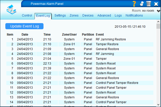
- display event log
- bypass sensors
- mute sirens
- sync time
- switch/dim X10 devices
- PGM device
- Special plugin features
- Support for Powerlink or Standard mode
- Notifications
- Siren & keypad devices supported
- Multi-language support (in progress)
Version history
- 1.0 March 11, 2013
- initial version with new engine
- 1.1 May 20, 2013
- new event log interface, incl. partition info
- added web handlers for retrieving log files
- improved support for wired zones
- improved message handling, incl. variable length
- added handling of 25 and B0 message
- support for multiple panels
- generate crash log file in case of plugin restart
- show which user is being called
Powerlink vs Standard mode
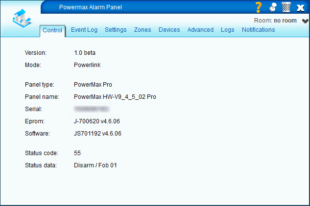 The Powerlink mode has the following advantages over Standard mode.
- All type of device settings can be read
- Serial, panel type, panel name, hw/sw version
- All devices can be created automatically, depending on the panel settings
- Automatic detection of sensor type (PIR, Magnet, Smoke sensor)
- Sensors created with panel zone names, incl. custom zone names
- PGM, X10, Siren, Keypad devices created automatically
- Panel updates are automatically processed
- No need to enter pin code (read from panel, not stored in plugin)
- Bypass function works directly on a sensor
Note: For Powerlink mode to work the enrollment procedure has to be followed. If you don't enroll the Powerlink on the PowerMax the plugin will operate in 'Standard' mode, and if enrolled in 'Powerlink' mode. On the newer software versions of the PowerMax the Powerlink enrollment is automatic, and the plugin should only operate in 'Powerlink' mode (if enrollment is successful). See 'Settings' below how to force the plugin to use 'Standard' mode if needed.
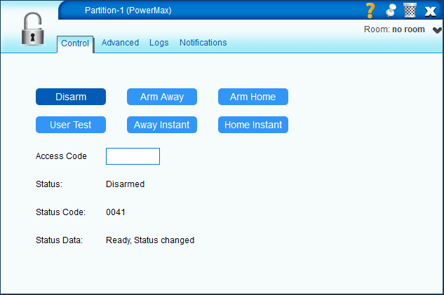
Screenshots (UI5)
Installation
Setting up a serial connection
- Connect a USB to serial cable between the PowerMax and Vera. Preferably use a converter with an FTDI chipset for this.
- Under 'Apps' > 'Develop Apps' > 'Serial Port Configuration' the serial connection should now be visible. Make sure the baud rate is set to 9600 (which is the default).
Configuring for first use
- Install the plugin from the MiOS Marketplace
- After installation the start-up of the device will fail, since no serial port has been selected yet.
- Go to the 'Settings' tab of the panel
- Select the serial port under 'Communicate using UART'
- Save changes
- Enroll the Powerlink module
- On the PowerMax panel, enroll the Vera as Powerlink. Note that this is done automatically on newer models. If another Powerlink device (or plugin) was enrolled, then that enrollment has to be removed first. Refer to your PowerMax manual how to do that.
- On start-up of the plugin the notification 'Reading panel settings' should be displayed. This means the plugin is in Powerlink mode and the panel configuration is being read. Depending on the PowerMax model this can take longer.

- In case enrollment is not successful the message 'Vera Powerlink not enrolled.' will be displayed and the plugin will switch to Standard Mode.
- Once all settings are read the notification 'Ready for use' will be displayed.
- Plugin settings can now be set according to desired behavior.
- See the section Configuration
Manual plugin update (optional)
This is only applicable if the plugin is NOT downloaded from the MiOS Marketplace.
- Upload the plugin files:
- In the Toolbox section open MiOS Developers >> Luup Files and upload all the files you downloaded. If the Restart Luup after upload check box is un-checked, check it, and click GO.
- Create the alarm panel device:
- Open Create Device.
- In the UpnpDevFilename input box enter D_Powermax.xml.
- Click Create device.
- Press 'Reload'
Configuration
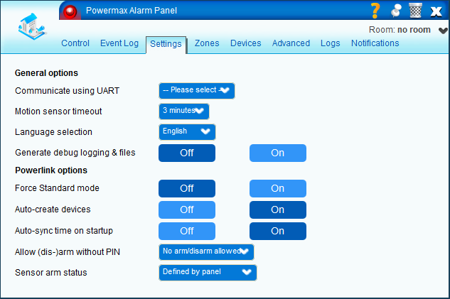
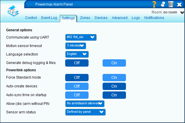 The following settings are available in the 'Settings' tab.
- General options
- Communicate using UART - select the USB UART interface for communication with the PowerMax
- Motion sensor timeout - select the number of minutes a motion sensor will be displayed as 'tripped'
- Language selection - select the language in which the status of the panel & partition is displayed
- Generate debug logging and files - When 'On', creates debug info as well as 'powermax_pdu.txt' and 'powermax_settings.txt' files
- Powerlink options (used in Powerlink mode only)
- Force Standard mode - When 'On', will force the plugin to use Standard mode and not enroll
- Auto-create devices - When 'On', reads the settings from the panel to create devices
- Auto-sync time on startup - When 'On', syncs time between Vera & PowerMax after each download (when starting the plugin)
- Allow (dis-)arm without PIN
- No arm/disarm allowed - A pin code is always needed to arm or disarm a partition
- Only arm away allowed - Only Arm Away can be done without using a PIN code
- Arm (Home) allowed - The partition can be armed without a PIN code, but Disarm needs a PIN
- Arm & disarm allowed - The partition can be armed and disarmed without entering a PIN
- Sensor arm status
- Defined by panel - If the panel configuration is such that arming with bypass is allowed, then the mode 'Always show bypass' is selected. If using a bypass is disabled in the panel settings, then the mode 'Always show armed live' is selected.
- Always show bypass - Shows on the sensor whether it is in bypass state or not. If the sensor shows 'Armed', then it can trigger an alarm, dependent on the partition state.
- Always show armed live - Shows on the sensor whether it currently 'armed live'. If the sensor shows 'Armed', then it will trigger an alarm. The 'Armed' state is dependent on the partition state and the sensor setting (e.g. interior, 24h, perimeter, fire etc.)
After a change in any of the settings press the 'Save' button to make the new configuration active.
Zones & devices
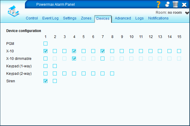
The information on zone type and panel devices can be set in the 'Zones' and 'Devices' tabs.
Zones
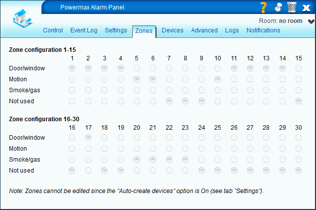
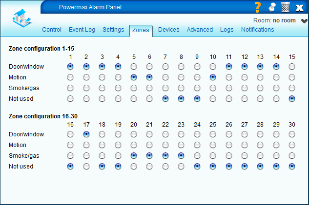
The zones and their types can be configured in the Zones tab. There are three types of sensors supported currently.
- Door/windows (magnet type sensors)
- Motion (PIR type sensors)
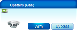
- Smoke/gas (smoke, CO2 sensors etc.)
In Powerlink Mode with Auto-config on, the configuration of zones is done automatically and the information cannot be edited.
Devices
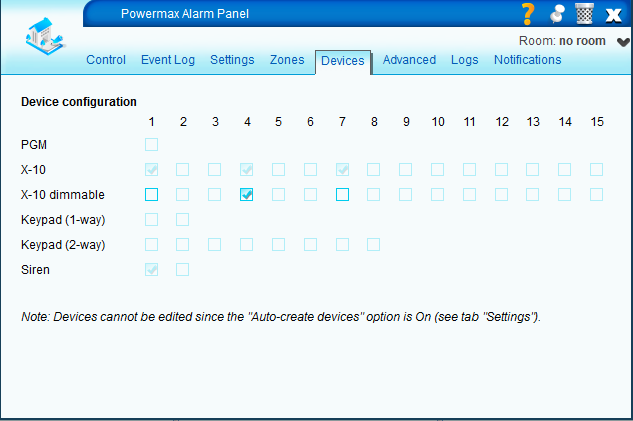
In the devices tab a number of devices can be configured. The following devices are currently supported.
- PGM - Configures a PGM switch device.
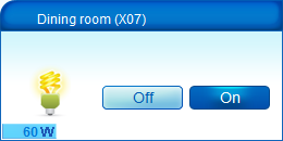
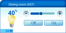
- X10 devices - Normally will become a switch, unless 'X10 dimmable' for the device is checked as well.
- Keypads (1-way or 2-way) - Will be automatically added if present, but have no function at this point.
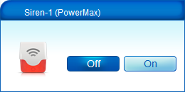
- Sirens - The siren will show if a siren is active or not. If one is active it can be muted by pressing the Off button. Muting one siren will mute all sirens (also the panel internal one). Note that sirens currently only work with beta firmware from MCV.
In Powerlink Mode with Auto-config on, the configuration of devices is done automatically and the information cannot be edited. Whether an X10 device is dimmable or not can always be adjusted.
After a change in any of the settings press the 'Save' button to make the new configuration active.
Notifications
Both the panel as the partition(s) have notifications available.
Panel
For the panel, the following notifications are available.

- Alarm type, being either
- Intruder
- Panic
- Emergency
- Tamper
- Fire
- Flood
- Gas
- Trouble type, being either
- Battery
- Communication
- General
- Jamming
- Power
- Telephone
Partition
For the partition, the following notifications are available.
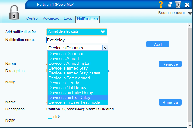
- Armed state
- Armed
- Disarmed
- Armed detailed state
- Disarmed
- Armed
- ArmedInstant
- Stay
- StayInstant
- Force
- Ready
- NotReady
- EntryDelay
- ExitDelay
- Alarm
- Active
- None
Advanced functions
When the debug option is 'On', the plugin will create a number of log files. As of version 1.1 the log files are prefixed with the device id (e.g. 123_powermax_pdu.txt). The 'pdu' log file will continuously be updates with messages that are being sent and received. The 'settings' log file will be filled on startup and contains the settings of the PowerMax panel. A 'crash' log file will be created if the the plugin gets in an undefined state and needs to restart.
As of version 1.1, the following web handlers can be called to retrieve log files. Examples are for device id 123.
- http://<vera_ip>/port_3480/data_request?id=lr_GetLuaLogFile (use with care!)
- http://<vera_ip>/port_3480/data_request?id=lr_GetPduLogFile123
- http://<vera_ip>/port_3480/data_request?id=lr_GetSettingsFile123
- http://<vera_ip>/port_3480/data_request?id=lr_GetCrashFile123
Attachments
-
powermax.jpg
(7.9 KB) -
added by nlrb 12 years ago.
Splash
-
panel_settings_config.png
(40.0 KB) -
added by nlrb 12 years ago.
Panel settings - needs serial config
-
panel_settings.png
(39.0 KB) -
added by nlrb 12 years ago.
Default panel settings
-
dev_dimmer.png
(10.1 KB) -
added by nlrb 12 years ago.
Device: dimmer
-
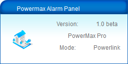
dev_panel.png
(7.5 KB) -
added by nlrb 12 years ago.
Device: panel
-
dev_siren.png
(8.9 KB) -
added by nlrb 12 years ago.
Device: siren
-
dev_sensors.png
(16.2 KB) -
added by nlrb 12 years ago.
Device: sensors
-
dev_switch.png
(9.2 KB) -
added by nlrb 12 years ago.
Device: switch
-
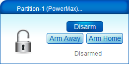
dev_partition.png
(10.2 KB) -
added by nlrb 12 years ago.
Device: partition
-
not_alarm_type.png
(30.1 KB) -
added by nlrb 12 years ago.
Panel notification: alarm type
-
not_armed_state.png
(33.7 KB) -
added by nlrb 12 years ago.
Partition notification: armed state
-
panel_control.png
(30.1 KB) -
added by nlrb 12 years ago.
Panel: control
-
partition_control.png
(24.6 KB) -
added by nlrb 12 years ago.
Partition: control
-
panel_devices_auto.png
(28.4 KB) -
added by nlrb 12 years ago.
Panel: devices (auto)
-
panel_devices_edit.png
(26.0 KB) -
added by nlrb 12 years ago.
Panel: devices (edit)
-
panel_zones_auto.png
(36.5 KB) -
added by nlrb 12 years ago.
Panel: zones (auto)
-
panel_zones_edit.png
(36.3 KB) -
added by nlrb 12 years ago.
Panel: zones (edit)
-
powermax_reading.png
(4.9 KB) -
added by nlrb 12 years ago.
Powermax notification: reading panel settings
-
powermax_ready.png
(4.8 KB) -
added by nlrb 12 years ago.
Powermax notification: ready for use
-
powermax_serial.png
(5.9 KB) -
added by nlrb 12 years ago.
Powermax notification: no serial connection
-
panel_eventlog.png
(45.8 KB) -
added by nlrb 12 years ago.
Panel: event log
-
dev_gas.png
(8.9 KB) -
added by nlrb 12 years ago.
Device: gas sensor


