
| Version 2 (modified by mcvflorin, 14 years ago) (diff) |
|---|
DSC Alarm Panels Plugin
Installation
- If the previous DSC plug-in was installed, then it is recommended to uninstall it first, and then remove the plug-in files from the via SSH
- Before attempting to install the plug-in, its recommended to connect the respective RS232 adapter, and set this up first in order to establish connectivity.
- Download the .zip file from this location
- Extract the 7 files to a location on your PC.
- Click the MiOS developers icon.
- Click the Luup files tab
- Scroll to the bottom of the window and click on the first browse button
- Navigate to the location of the previously saved files and select the first file
- Repeat this using additional browse buttons for the remaining 6 files.
- Check the "Restart Luup after upload" box and click Go
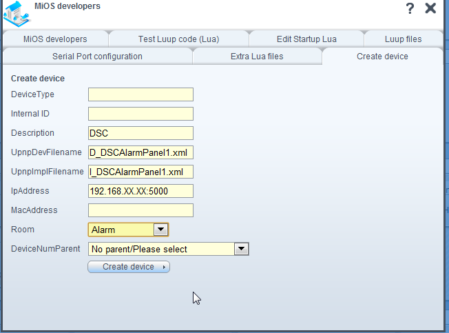
- After the Engine restarts, click on the create device tab of the MiOS developers icon.
- In the Description field, enter a name for the plug-in, similarly in the UpnpDevFilename field enter D_DSCAlarmPanel1.xml and in the UpnpImplFilename field enter I_DSCAlarmPanel1.xml
NOTE: It is critical to enter the file names exactly as above, this includes the case sensitivity!
- If this is being used with a WIZnet or Roving Networks IP to Serial adapter that’s already been configured, then at this stage the IP and port number of the device can also be entered in the IpAddress field (e.g. 192.168.8.23:5000)
- Click Create device and then exit

NOTE: when the engine finishes loading, and an IP address was entered, hopefully if everything is working correctly, there should now be 8 new devices created which will represent the Panel (parent device), 1 partition and 6 Zones.
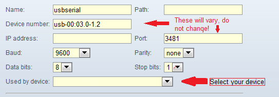
If the IT100 has been connected to a USB to RS232 converter then this will now need to be set up as follows:
- Presuming the Adapter has already been plugged in and recognized as a device and port in the MiOS developers / Serial tab.
- Select the correct Serial device, and enter the following settings which represents the default IT100 baud rate:

- In the "Used by Device" dropdown, select the name of the device that was entered during plug-in creation.
- Exit this screen and then Save.
- Again if everything is working, the 8 devices should have been created.
Additional Setup
- To configure the correct Partitions and Zones, select the parent device (as named during the creation process).
- Click the advanced tab
- Under Partitions by default there will be 1 present, if additional partitions are to be set up then enter them in sequential manner separated by a comma as follows: For two partitions enter 1,2 For three partitions enter 1,2,3 etc etc...
Under the different Zone fields, enter the zone numbers in the same type of sequence. By default it will display 1,2,3,4,5,6 in DoorZones.
Note you will need to know which Zones are set up which on your panel. They may not be in sequence (per the above), and can be entered depending on their type in any of the three Zone variables.
If remote Arming and Disarming is not required from Vera, then exit and save; however if this is required then stay in this screen and enter one of the following into the EnableRemoteArm variable:
- disarm (Least secure as all functions are available including disarm)
- stay (This will enable stay arming and away arming, but not disarm)
- arm (Will only enable away mode arming)
NOTE: disarm is the least secure and enables all remote arming features.
After entering any of the above, exit and save.
To set the time on the panel, in the main tab of the device, enter your PIN and click "Set Time"