
NOTE! This page is no longer updated
You will find the latest information about MySensors here:

Arduino Gateway
Installing the Arduino Vera plugin
The latest version of the Vera plugin can be found here.

- Download all *_Arduino*.* files and upload them in Vera under APPS->Develop Apps->Luup files (you can skip the subfolders if you don't plan to use these sensors).
- To create the Arduino Plugin device go to APPS->Develop Apps->Luup and enter "D_Arduino1.xml" in "Upnp Device Filename" and press "Create Device"
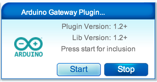
- After the usual reload/refresh ritual the Arduino root device should pop up.
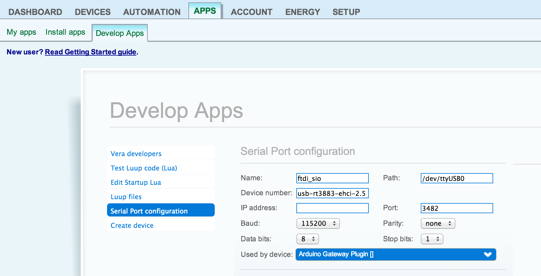
- If you have your Arduino board plugged into Vera you should now configure which serial device to use. See image to the right. Set baudrate to 115200.
Installing Arduino Gateway Software
Install all Arduino libraries found here in your Arduino IDEs library location.
Download the Arduino sketch for the Serial Gateway version here and download it to your Arduino Nano.
You really don't need to configure anything in this sketch. Just download it and connect the Arduino to your Vera using usb-connector. Please note that only Arduino Nano module have a serial chipset recognized automatically by Vera.
If you prefer the Ethernet Gateway version it's found here. Follow connect instruction in the head of sketch. (See: http://forum.micasaverde.com/index.php/topic,23093.0.html)
Wire & casing things up
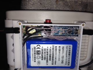
 You only need to connect the radio chip to the Arduino. Follow the instructions in ConnectingRadioModule.
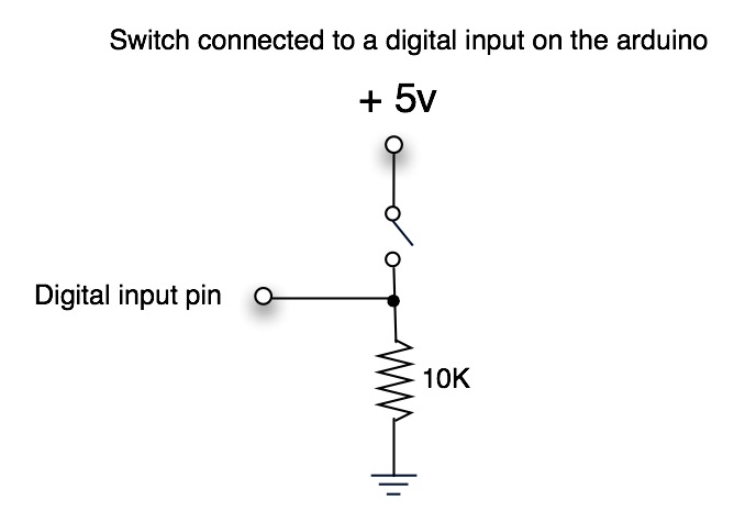
As an option you also can connect inclusion button & indicating leds. Pin to be used by button is defined inside SerialGateway? sketch as #define INCLUSION_MODE_PIN 3. Actually it is hard to redefine it because sketch is using the particular interrupt handler. Connect button between +5V and digital pin 3 with a 10k pull down resistor to GND (see image).
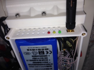
There are 3 led types supported - RX/TX/Error. Use them to have a visual feedback during radio activity. Radial 3mm green/yellow/red leds could be a good choice. Your should use 3 resistors 270R-510R. Each led is connected by anode to +5V pin and cathode is connected through a resistor to a digital pins 6/5/4 respectively for RX/TX/Error. Pins can be re-configured inside SerialGateway? sketch at this line:

// Start gateway with include button and led blinking functionality enabled (see documetation)
Gateway gw(9, 10, INCLUSION_MODE_PIN, INCLUSION_MODE_TIME, 6, 5, 4);
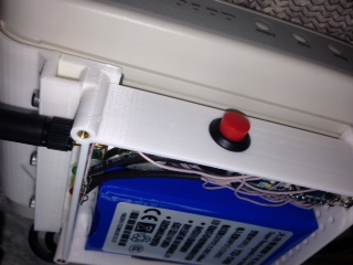
There is no special requirement for the casing, you can use any case suitable for your setup. A nice 3d model for 3d printer can be found here http://www.thingiverse.com/thing:159417.
Hardware - Purchase guide
This is the stuff you need to purchase to build the ArduinoGateway. Note that I've provided links to the things I bought during the development. You might find it cheaper somewhere else. Also note that you might need to buy more than 1 product to get the price specified.
1x Arduino Nano with serial interface and usb connector

8x Dupont female to female jumper cable
1x NRF24L01+ wireless data transmission module 2.4Ghz
TOTAL PRICE: $7,99 + $0.93 + $0,6 = $9.5
Attachments
- serial.png (177.5 KB) - added by hek 12 years ago.
- veraplugin.png (57.6 KB) - added by hek 12 years ago.
-
gateway1.JPG
(33.6 KB) -
added by axill 12 years ago.
gateway case 1
-
gateway2.JPG
(41.2 KB) -
added by axill 12 years ago.
gateway case 2
-
gateway3.JPG
(33.6 KB) -
added by axill 12 years ago.
gateway case 3
- digital_button.jpg (30.7 KB) - added by hek 12 years ago.