

Introduction
The DSC Alarm plug-in enables the integration of Vera and the DSC alarm and he whole integration consists of three functional components and they are:
- VERA - A Vera (3, Lite and Plus) UI5/UI7 or UI4 (Vera 2 only) with the DSC plug in installed;
- DSC Alarm System - The DSC Power Series Alarm system current compatible model include the PC1616 (16 zones), PC1832 (32 zones) and PC1864 (64 zones) panels; and
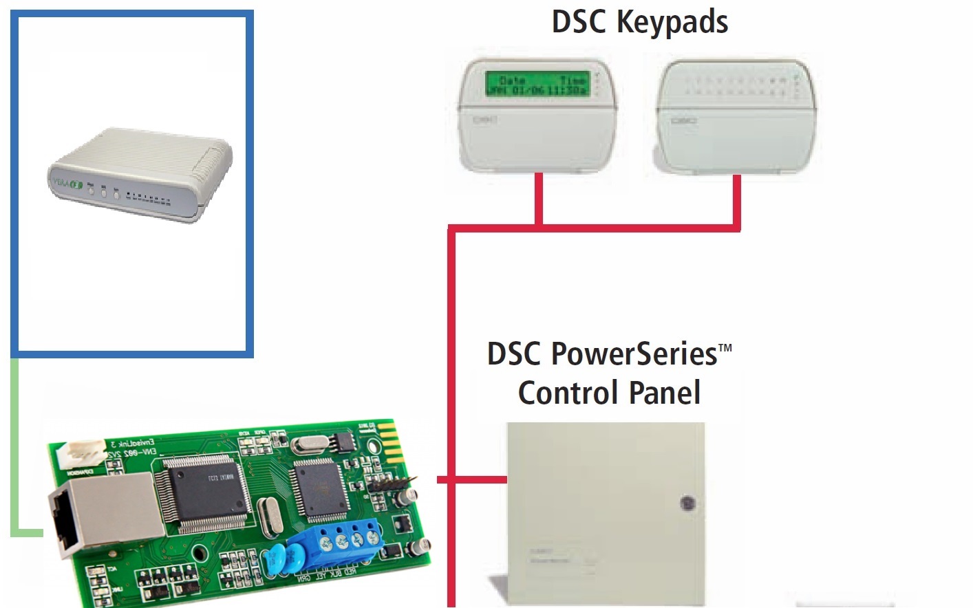
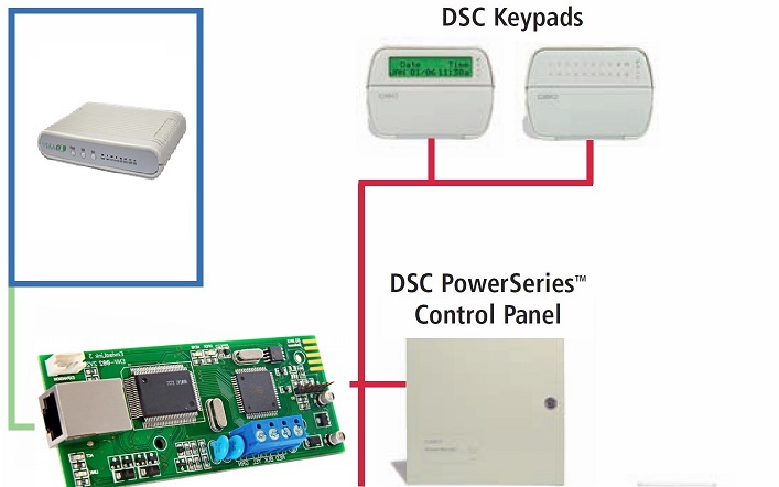
- Integration Module – This is the interface that Vera uses to communicate with the alarm system. The integration module is wired to the Alarm System’s Keybus in the same manner as a keypad or other alarm modules. This connection may be either directly wired to the Alarm Panel or indirectly via another keypad or module that is (daisy chained) wired back to the Alarm Panel. Depending on the integration modules connection, this will determine how the integration module communicates with your Vera. Connections are covered in more detail throughout this document.
Supported Modules - (Latest)
Envisalink EVL2/3/4 (Network attached) directly is connected to your home network. The EVL has an internal web portal, is firmware upgradable and can provide external access via the Eyes-on site or various mobile phone applications. More details can be found at Eyez-On which includes detailed specifications and reviews
EVL2/3/4 Ethernet (IP) Integration Module

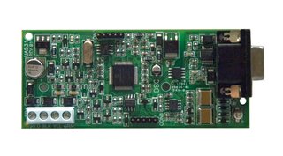
DSC IT-100 (Serial) integration module was the initial interface to enable third-party applications and system to communicate with Power Series control panels. The DSC IT100 provides an RS232 serial connection that can be either connected directly to your Vera utilizing a USB to Serial adapter or over the Ethernet utilizing either an IP to RS232 or a WIFI to RS232 adapter.
DSC IT100 RS232 Integration Module

If the IT100 is to be used with Vera, the user will have to decide the best method to interface it with your system. This can be accomplished with any of the following options:
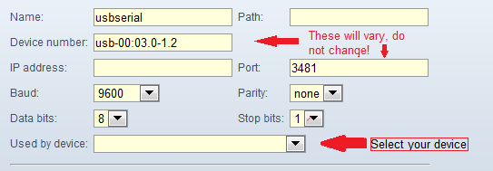
- Direct Connection to a USB to RS232 serial adapter thats supported by Vera such as this one.
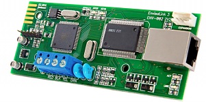
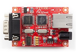
- Wired Ethernet Connection via an IP to RS232 serial adapter such as WIZnet device like this one.
- WiFi to RS232 serial adapter such as this one.
Figure 3 – WIZNET WIZ110SR IP to Serial (RS232) Adapter

Supported (Older models) Envisalink 2DS/IP170 - (Network attached) are discontinued model similar to the Envisalink EVL3 and with lower hardware specifications and currently provides the same functions as the EVL3. See here
Not Supported
- DSC IP100 - See here for plugin
- DSC TL150, TL250, TL265 TL350 or the DSC Alexor interfaces
Connection

The DSC Alarm plug-in is a Luup component that connects Vera to a DSC PowerSeries alarm panel such as the PowerSeries 1616, 1832 and 1864 panels, via an IT-100 or Envisalink IP170/2DS Keybus module. Through this interface, events occurring within the Alarm Panel are exposed to Vera including the status of any attached Doors, Windows, Motion Sensors.
Each of these is exposed as a Motion Sensor to Vera, so that standard Scenes (Lights, Notifications, etc) can be established in Vera based upon events occurring within the Alarm Panel.
Additionally, the interface exposes the current Armed State, Stay Armed State and whether the Alarm is in Breach. These are also exposed in a Scene-aware manner so that Vera can respond to them.
WARNINGS:
- This plug-in is designed for UI5 and UI4, prior versions of Vera's Firmware will not work.
- If the Plugin is updated from the files contained here >0.35, or if it automatically updates from an app store based version, then it will change the device ID's of any sensors that are set up as "DoorZones" The above will only be a problem if these doorZone sensors have been set up at all as triggers for scenes, and these will have to reset after updating To avoid the above scenario the following changes should be made prior to updating:
If you currently have a setup with the following initialization parameters
DoorZones=1,2 MotionZones=3,4,5
Then they must be changed prior to the update being made as follows,
DoorZones= MotionZones=1,2,3,4,5
They must all be set up under the MotionZones parameter (the front, ordering is important) Once the above is saved, then it will be safe to proceed with updating the plugin.
Terminology
Zone::
a specific sensor in the Alarm Panel, such as a Window, Door or Motion Sensor. These may either be hardwired, or wireless, depending upon the type of sensor.
Area / Partition::
a collection of Zones. Typically there is a single Area in a house. Larger houses are often split into separate Areas (Upstairs vs Downstairs). External buildings such as Garages and Guest houses are also candidates for additional Areas.
Keybus::
DSC Security proprietary protocol. This protocol is used for communications between DSC System components, such as the IT100, T-Link IP modules, Zone Expanders, Envisalink IP170/2DS, and the System Keypads.
Remote control::
a Key chain remote control device, used to Arm (Lock), Disarm (Unlock) or set a Panic Alarm
Entry Door::
a Zone (door) with a grace period delay attached to it. The Alarm will not go off during the grace period.
Breach::
the Alarm is currently going off, either with a Bell, or a Silent Alarm.
Arm::
the act of setting the Alarm Panel into the "I'm leaving" state.
Stay Arm::
the act of setting the Alarm Panel into the "I'm staying" state. In this state the Motion Sensors don't trip Alarm Breach.
Force Arm::
same as Arm except that some Zones may be left Open
Instant Arm::
same as Stay Arm except there is no grace period on opening an Entry Door.
Virtual PGM::
a special type of Zone defined within the Alarm Panel. The Alarm Panel can be configured to establish the conditions under which a Virtual PGM [Zone] is triggered and/or reset. Virtual PGMs events are supported in the code, but are disabled by default to make the UI simpler.
One Touch or Quick Arming::
a variant on the Arming modes that typically doesn't require a PIN Code to be entered to initiate the Arming request.
Messages
Depending upon the specific model of Alarm Panel, there will be support for different numbers of Zones, and Areas. However at startup of the DSC Alarm plug-in, upon successful connection to the Alarm Panel itself, the plug-in will default to creating 6 zones (1,2,3,4,5,6) regardless of how many Zones are configured, and how they may be numbered. The Plug-in by default will also create only one partition despite how many are configured. Once basic communication has been established, it will be necessary to configure the plug-in with the respective zones and partitions.
These low-level messages are varied, but include:
- Retrieve a Zone Label
- Retrieve a Partition Label
- Read the status of a Zone (open/closed)
- Read the status of an Area (armed/force-armed, stay-armed/instant-armed, alerting/breach)
- Zone status change events
- Zone status change events
- Request Arming / Force-Arming
- Request Stay-Arming / Instant-Arming
- Trigger Alerting / Breach
- Remote control.
The DSC Alarm Plug-in processing
Startup processing
The Startup processing for the Alarm Panel plugin looks roughly like:
- Establish Communication with the Panel
- Create 1 partition and attempt to read the partition label.
- Create 6 Zones as child devices in the System, and attempt to read the zone labels.
- retrieve the current state of each Zone, and "set" it into Vera
Event processing
After startup, the system is set running. It receives events and, for those of interest, it translates them into MotionSensor values to set upon it's Child Devices, in addition to setting Variables directly on the Alarm Area device
During Scene creation, the following Events are exposed by each partition:
- Partition is Armed
- Partition is Stay Armed
- Partition is Breached
- Partition is Disarmed
During Advanced Scene creation, the following Actions are exposed by each "Area" device:
- Arm Partition - Submit a request to Arm the Alarm Partition (with PINCode)
- Quick Arm Partition - Submit a request to Quick, or "OneTouch", Arm the Alarm Partition (no PINCode required)
- Stay Arm Partition - Submit a request to Stay-Arm the Alarm Partition (with PINCode)
- Quick Stay Arm Partition - Submit a request to Quick, or "OneTouch", Stay-Arm the Alarm Partition (no PINCode required)
- Disarm Partition - Submit a request to Disarm the Alarm Partition (PINCode required)
- Medical Panic - Submit a request to trigger the Alarm Partition's Medical Panic - UI4 and above only
- Fire Panic - Submit a request to trigger the Alarm Partition's Fire Panic - UI4 and above only
- Police Panic - Submit a request to trigger the Alarm Partition's Police Panic - UI4 and above only
NOTE: The Alarm plugin code disables these Actions by default. They must be enabled prior to using them in a Scene definition. Since MiOS stores these scene definitions, including any Parameters supplied (eg PINCode) use of these features may constitute a security risk - use at your own risk.
Alarm Area Variables
This Alarm Panel implements a DeviceType that gives it the following Variables (through it's ServiceStateTable). These can be used for Luup scripting:
- Disarmed - Set whenever the Alarm Area is Disarmed (not Armed and not StayArmed)
- Armed - Set when the user requests the Alarm Area to Arm, Force Arm, Stay Arm or Instant Arm the Area
- StayArmed - Set when the user request the Alarm Area to Stay Arm or Instant Arm the Area
- Breach - set when the Alarm Area is in Breach (Siren, Silent etc)
Installation & Setup
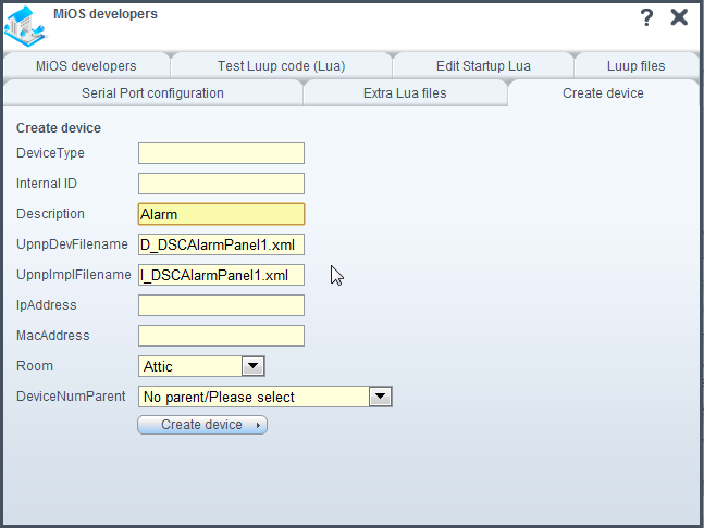
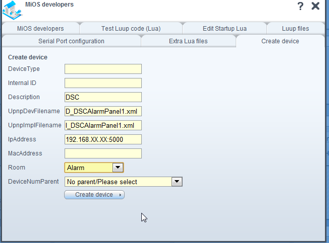
- Instructions for UI4 installation
- Instructions for UI5 installation
Additional Setup
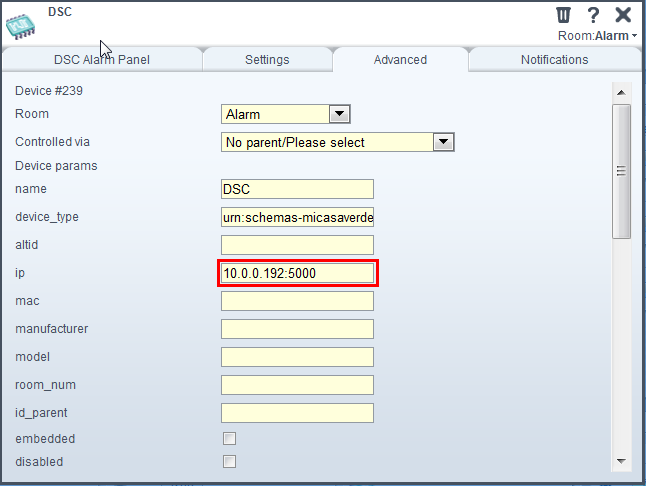
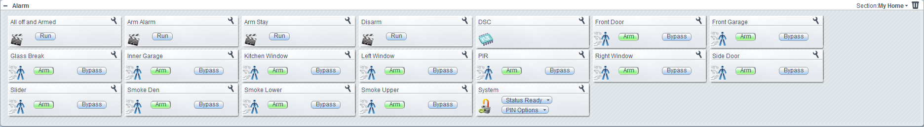
- To configure the correct Partitions and Zones, select the parent device (as named during the creation process).
- Click the Advanced tab
- Under Partitions by default there will be 1 present, if additional partitions are to be set up then enter them in sequential manner separated by a comma as follows: For two partitions enter 1,2 For three partitions enter 1,2,3 etc etc...
Under the different Zone fields, enter the zone numbers in the same type of sequence. By default it will display 1,2,3,4,5,6 in DoorZones.
Note you will need to know which Zones are set up which on your panel. They may not be in sequence (per the above), and can be entered depending on their type in any of the three Zone variables.
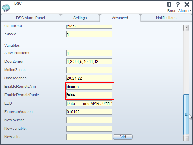
If remote Arming and Disarming is not required from Vera, then exit and save; however if this is required then stay in this screen and enter one of the following into the EnableRemoteArm variable:
- disarm (Least secure as all functions are available including disarm)
- arm (Will enable away and stay arming)
NOTE: disarm is the least secure and enables all remote arming features.
After entering any of the above, exit and save.
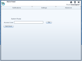
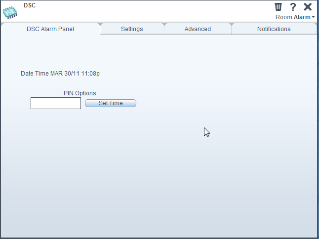
To set the time on the panel, in the main tab of the device, enter your PIN and click "Set Time"
Zone labels by default will use the default ones programmed in the panel, if labels were never programmed, or were programmed before the IT100 was installed, then the default labels for the sensors the plugin creates will be named "zone 01, zone 02 etc etc, and they cannot not be renamed by default. It is best to try and rectify this with the alarm itself first, however this behavior can be changed by editing the EnableManualLabels variable in the advanced tab of the alarm parent device from false to true and then performing a save at the top of the dashboard; it will then possible to rename.
If its preferred that the plugin uses the default mechanism of using the labels from the Alarm System, there are usually several ways to rectify the above behavior without changing the above variable:
- If labels have previously been programmed in a keypad, then attempt a label broadcast from the keypad they were originally programmed from by entering *8[Installer code]*998*
- If labels were never programmed then they can be programmed them from an alpha numeric keypad and a subsequent label broadcast
- Program the labels to the panel using DSC DLS software
Troubleshooting IT100 issues
If after setting everything up the plugin does not seem to work, then its recommended to try some of the following:
- If using a USB to serial adapter, check that its a supported type.
- Check that the cabling is correct, or replace the serial cable (if used); note that the IT100 does not need a Null modem cable and the pins of the DB9 should be wired 2>2, 3>3 and 9>9
- If the plugin was downloaded from the UI4 Marketplace, then delete it and reinstall the plugin from the files linked here.
- If using a WIZnet adapter make sure its setup correctly as per this post and especially that its "Operation Mode" is set up as Server.
- ToDo? ...Add more
Scene Scripting
When defining scenes, the following actions are exposed in Advanced Scene mode:
- RequestArmMode(State, PINCode)
- RequestQuickArmMode(State)
These have the parameters for the ArmMode Parameter which, in UI5, must be typed in exactly as below:
- Disarmed - The Partition is disarmed.
- Armed - The Partition is currently armed, or in an "away" mode.
- ArmedInstant - The Partition is currently armed, or in an "away" state, Entry triggers Alarm immediately.
- Stay - The Partition is in an "at-home" mode, delays are permitted on Entry doors.
- StayInstant - The Partition is in an "at-home" mode, Entry doors trigger Alarm immediately.
- Night - The Partition is in an "at-home, at-night" mode, delays are permitted on Entry doors.
- NightInstant - The Partition is in an "at-home, at-night" mode, Entry doors trigger Alarm immediately.
- Force - The Partition is in an "away" mode, but one or more Zones are open.
- Vacation - The Partition is currently armed, or in an "away" mode.
Discussions
References and Links
- IT100 developer guide
- 2DS TPI developer guide
- A good base system
- Lua 5.1 Reference Manual
- Lua-users Lua Tutorial
- DLS programming software for use with serial cable and PC
- Build a DLS programming cable
- Programming instructions for a Power Series panel

Attachments
- main_panel1.png (11.5 KB) - added by javier_guerra 15 years ago.
- partition_panel.png (10.1 KB) - added by javier_guerra 15 years ago.
- arming2.png (24.7 KB) - added by strangely 14 years ago.
- create.png (27.7 KB) - added by strangely 14 years ago.
- createdevice.png (29.3 KB) - added by strangely 14 years ago.
- files.png (37.0 KB) - added by strangely 14 years ago.
- ip.png (28.9 KB) - added by strangely 14 years ago.
- IT100.jpg (13.8 KB) - added by strangely 14 years ago.
- remotearm.png (29.8 KB) - added by strangely 14 years ago.
- room.png (74.3 KB) - added by strangely 14 years ago.
- time.png (18.4 KB) - added by strangely 14 years ago.
- zones.png (30.1 KB) - added by strangely 14 years ago.
- keypad.jpg (25.8 KB) - added by strangely 14 years ago.
- 232.png (16.2 KB) - added by strangely 14 years ago.
- 2DS.png (78.0 KB) - added by strangely 13 years ago.
-
EnvisaLinkTPI-1-00.pdf
(89.7 KB) -
added by strangely 13 years ago.
2DS TPI developer guide
-
Connection ELV3.jpg
(163.6 KB) -
added by brientim 12 years ago.
Schematic DSC and EVL3
- WIZnet.2.jpg (26.3 KB) - added by brientim 12 years ago.
- ExampleConnection.jpg (61.3 KB) - added by brientim 12 years ago.
- EVL3.jpg (26.0 KB) - added by brientim 12 years ago.
-
WIZnet.jpg
(26.3 KB) -
added by brientim 12 years ago.
WIZNET